
Apple II europlus
Restoration
I acquired an Apple II europlus computer from Marktplaats.be in unknown condition for €200.
The Apple II europlus is the European version of the Apple II plus.
It has a 230Vac power supply and PAL monochrome video.
It is for the most part identical to the Apple II plus.
It came installed with a Apple Disk controller, an Apple Disk Drive II and language card .
I found a small vintage 9″ Hitachi monitor, on eBay, of the era that matched some of the many pictures of Apple II systems.
Got it for £80, but it arrived with a cracked front frame. This probably due to soft handling during transport (NOT!!!)
When testing the monitor, it started up properly but after a while it stopped giving picture.
More repairs required ….
A quick check showed that the computer did not boot. However, the power supply was OK, with all voltages within tolerance.
At this time it looked like I a ran out of luck.
How to proceed with diagnosing what is preventing it from booting properly!?
Luckily, I had 2 spare Apple II plus main boards which I actually bought to harvest components of for my coming Apple I build.
I thought I could harvest the IC sockets from this PCB for use on the Apple I, but I later noticed that these weren’t the correct type after all. (grrrr…)
I decided to go for cleaning first, perhaps there was some IC socket trouble going on.
Swapping components on any Apple II or II+ is easy as the Apple II plus main board is fully socketed.

Furthermore, I needed a good schematic reference document to help me debug this computer.
Although there are many sources available for the schematics of this computer, I settled for ‘Understanding the Apple II’ by Jim Sather. You can find this book online here.
This book turned out to be a good find as it helped me resolve quite some issues.
The Apple II Reference manual is also a good source for the schematics but does not contain any detailed circuit description.
Step 1: Opening the Apple II computer!!!
Opening an Apple II/II plus/II europlus computer is easy.
1. Get the lit of the case, so that you can see the main board and the power supply.

2. Turn in over and remove the 10 screws holding the bottom plate to the Apple II case.

3. Attention!!!: take care to safely disconnect the keyboard ribbon cable before completely separating the case from the bottom plate.
4. Disconnect the power supply by pulling out the power connector top left on the main board (you need to squeeze TOP+Bottom of the connector to be able to remove)
5. Disconnect the speaker cable from the main board
6. remove any card plugged into the extension slots top of the main board and place these on a ESD protected surface.
7. Remove the 4 screws above the extension connectors if you have a later Apple II europlus.

8. Remove the nut in the middle of the main board placed between the ROM’s and the RAM’s (be careful to store the nut and washer in a safe place).
9. Squeeze the nylon struts and gently lift the motherboard PCB up. There are 5-6 of these to take care of.
You have the PCB free If all went correctly. Place the main board PCB on stable ESD protected surface.
10. Now is the moment that you can remove the power supply by removing the small 4 screws.
This makes cleaning the bottom plate a lot easier.
Step 2: Solving the Boot problem
Step 2.1: Cleaning the main board
First, we will address the boot problem!
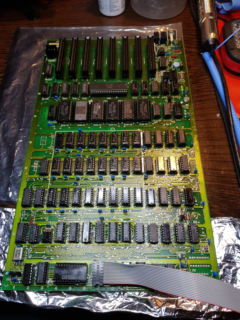
The motherboard is dirty, as you can see.

Unmount all ICs and put them in an organized way on a ESD matte so that you can mount them easily after cleaning.
I always put the IC’s in the same position as if there placed on the main board.
Please note that the IC positioning on the PCB is done by means of the ‘ROW’ Letters ‘A’ through ‘K’ marked on the left-hand side of the main board. The Bottom side has the column numbers ‘1’ through ’14’.
For example position C3 = RAM chip, the CPU has position ‘H7/H8’, F12 is a 74LS138, etc…


2. rinse the motherboard with warm water (35 to 45°C) to remove most of the dirt.
Why warm water? Because it will dry much quicker and is much more efficient in removing dirt. Do not use any detergent!
3. Rinse bottom plate, take care not to get the loudspeaker wet. (The cone is made of cardboard and can damaged by getting wet)
4. Put the motherboard in a warm place and let it dry out.
5. Clean the main board contact cleaner, after drying the motherboard with a piece of cloth. Take care not put contact cleaner on any label and date marking.
6. Generously spray the IC socket contacts and let soak for a few minutes
7. Remove the excess contact cleaner from the main board with a fresh piece of cloth.
8. Put the IC’s back in their respective sockets.
Note, that Woz was so nice as to leave all IC types marked on the main board for you to follow and to check. When doing this action, take care of ESD hygiene. Best to work on a ESD matte or ESD free plastic bag.
Take care that no pins are bended when pushes them into the sockets. Some ICs will need some convincing when putting them back in the sockets. If they do not fit, just put them on their side with the pins making contact to the ESD matte and gently roll them to bend the pins to make them fit easier into the IC socket.
Make sure that your hands/fingers are ESD free by means of earthing you wrist or prior to manipulating the IC’s touching the ESD matte each time you want to pick up an IC.
Please note that TTL IC’s of the 74xxx type a made with a bipolar technology making them very ESD tolerant and no real ESD care needs to be taken. The ROM’s, memory and microprocessor are very sensitive to ESD! (Made using MOS tech)
9. Do the same for the language card and the disk controller.
Great, now all the ICs are back in place and placement checked against the type markings on the PCB.
Step 2.2: Debug the Boot problem
Hook up the power supply to the motherboard and connect a monitor.
Connecting the speaker is also a good idea as the beep at boot will tell you that the main board is at least doing something.

Time to attempt to boot now!
And…. no success!!! All I get is a nice crash screen and nothing more.
First, I checked the power supplies first = all check out OK!
Feel the heat of each IC. Mostly, when you can keep your finger on the IC without burning it shows that it might be OK.
I found one ROM which is markedly hotter than the other ROM’s. (But didn’t burn my finger)
Time to start check the CPU reset (active low pin 40 on the CPU), test by using a multimeter or oscilloscope = Reset checks out OK!
The reset signal should stay low for a short time after power on.
Check the main CPU clock with an oscilloscope (1MHz square wave or with your multimeter on Vdc should show 2 – 2.5Vdc)
The clock also checked out OK!
Looks like some IC’s are broken.

First, I checked the hot ROM (ROM-F0).
Swapped one from a regular Apple II+ PCB.
Boot test again and this I get the prompt.
Now it’s time to hook up the keyboard and give it a try!
Made a small program to test the keyboard and the motherboard.
No problems! The “Hello World” program runs.
Step 3: RAM Test
It seems that RAM bank 0 is OK, since the main board is booting now.
This does not mean that RAM 0 is 100% certified OK, though.
But it is a positive step forward.
If this would not be the case, then probably there is a problem with one or more of the bank 0 RAM’s.
These RAM bank 0 is located on row ‘C’ of the Main board. (see the letter marking on the left side of the main board).
At this point I always like to do a quick test on the RAM’s by means of a small basic program.
You will need to plug a RAM chip (4116 type) from some other main board or the language card to complete this test.
This has the advantage that nothing else needs to be hooked up to the main board, although it can take some time to complete.
It test for following bit patterns: 0dec = 00000000bin, 85dec = 01010101bin, 170dec = 10101010bin, 255dec = 11111111bin
10 HOME
20 N=3000:?N;" ";
30 IF N>49151 THEN GOTO 120
40 POKE N,0:I=PEEK(N)
50 POKE N,85:I=I+PEEK(N)
60 POKE N,170:I=I+PEEK(N)
70 POKE N,255:I=I+PEEK(N)
80 IF N/256 = INT(N/256) THEN ?N;" ";
90 N=N+1
100 IF I=510 THEN GOTO 30
110 ?"ERROR @ ";N;" ";I
120 END
This small program will test memory locations 3000 to 49151.
3000 = bottom memory address, the basic program and other vital info to make Apple II lie below this address.
49154 = this the top of the address range for 48k RAM machines, 16383 for 16k RAM and 32767 for 32k RAM machines.
It will stop upon finding the first memory error and print the address of the faulty memory location on screen.
It also provides a clue to which bit(s) are faulty at the detected address.
Bank 0 = addresses below 16384
Bank 1 = above 16383 and below 32768
Bank 2 = above 32767 and below 49152
Variable I contains the sum of memory location test.
If all is OK I = 510 = 0 + 85 + 170 + 255.
if ‘I’ does not equal 510 then something went wrong at the tested memory location.
for instance a bit is locked HIGH, then I can have any of the following 8 values:
bit 0 = 512; bit 1 = 514; bit 2 = 518; bit 3 = 526; bit 4 = 542; bit 5 = 574; bit 6 = 638; bit 7 = 766
If a bit is forced LOW then the error sequence becomes:
bit 0 = 508; bit 1 = 506; bit 2 = 502; bit 3 = 494; bit 4 = 478; bit 5 = 446; bit 6 = 382; bit 7 = 254
If multiple bits are faulty then the above error values will still be different.
In the case of this computer, I found out that 3 memory chips where faulty.
One in bank 1 and two in Bank 2, luckily bank 0 seems OK.
The physical RAM chip can be located as follows:
1. Bank 0 = ROW ‘C’, Bank 1 = ROW ‘D’, Bank 2 = ROW ‘E’
2. Bit 0 = Column ‘3’, Bit 1 = Column ‘4’, ……, Bit 7 = Column ’10’
After swapping out the bad RAM IC’s, I did the RAM check again, this time with 0 error.
Mind you, if you do not have any spare RAM IC’s you can try convert your computer to 32kB by only populating RAM Bank’s 0 and 1.
Bank 0 always needs a full complement of RAM IC’s. The computer cannot operate without bank 0.
Now it’s time to put the language card back, after removing the memory chip (board location E3) back that we borrowed to be able do the RAM check!
Boot up and do the “hello World !!!” test again which went well.

After this it’s time to try to run a complete diagnostic on the main board. For this we need an Apple Disk II + Disk Controller board + Apple Diagnostics or Apple II Confidence floppy disk(s). I got some copies of these programs from eBay.

Make sure to put the disk controller PCB in extension slot 6 and connect the drive to the Drive I connector. Make sure its properly plugged with the cable going away from the Disk controller PCB. (See photo below)

Boot Up the Apple II europlus and the disk will start to run and make noises. Insert the diagnostics or Confidence program disk and run the RAM test. (See photo, left is diagnostics program, right is confidence program)

Both RAM test show that all is ok now!
Time to build the computer back to normal again!
Looks like it’s a brand-new computer now!
Repairing the broken frame took some doing.
I had to unmount the complete monitor to get to the broken frame.
I glued the frame with Loctite glue and re-enforced the frame with fiber which I also fixed with Loctite glue.
After this I used putty to fill in the crack and sanded the frame to get a smooth surface.
After this I painted the frame with humbrol ‘Dark Grey’ emanel paint.

I also could restore the monitor to functioning condition, it was a 12Vdc linear regulator that had partially failed.
Replaced with a LM7812 and the repair is complete now.

Have Fun!!!
Tips
ESD Hygiene!
MOS chips are sensitive to ESD. Especially the old chips from the 70ties and 80ties.
This means they can break down just by touching them.
Sometimes they get damaged, but function loss occurs a few months to a year after improper handling.

you need to handle these IC’s (Integrated Circuit) with care, by preference use an anti-static matte. You can also use an anti-static plastic bag (like the ones used to package electronic components) or aluminum foil.
These can be found in many online stores.
The most risk for ESD to happen is when the air humidity is low, like in winter or near dry places like a dessert. Always touch, with your fingers from both hands, the anti-static matte or aluminum foil/anti-static plastic bag before handling/touching these IC’s!
Attention!
Do not power any PCB when place onto the aluminum foil!
I managed to do this with one my TI99/4A power supplies with a broken power supply as the result! And of course, more repairing to be done…
Latest Posts
Follow Me
Get new content delivered directly to your inbox.
